BUILDING THE 600 OHM BALANCED-LINE VARIABLE ATTENUATOR
by Mark King for Proworkshop.com
TWO CHANNEL BALANCED-LINE VARIABLE ATTENUATOR
RACK MOUNTED DIRECTLY BELOW API 2500
THE PROBLEM
I am a big fan of the Warm Audio EQP equalizers. The Proworkshop studio has a pair from the first production run which we bought for tracking use in the studio. Once I heard them in the mastering-loop of our Neve mixer I knew this pair was doomed to stay there because they added so much power and tone to the stereo mix.
Newer production units from Warm Audio include a variable-gain trim-pot control on the back of the unit so you can match two pieces for stereo use. The pair we're using in the Proworkshop mastering system does not have these gain controls.
With the gain control located on the rear of the new Warm models the options for adjustment are still limited unless it's very easy to get to the rear of your rack to tweak the screwdriver-adjustable trim pots.
THE ATTENUATOR SOLUTION
I decided to build a precision level-control with variable attenuation knobs on the front of the unit for easy access and adjustment. The biggest impediment to accomplishing this is the use of balanced-lines for the interconnecting audio-signals and how to make them continuously adjustable without wrecking the tone of the signal passing through them. If possible I wanted to achieve all this without any additional active electronics or circuitry which could add more noise or compromise the audio.
During the engineering phase I considered many different ways to accomplish what I wanted to achieve. Typical dual-gang potentiometers do not provide the precision for this job without distorting the audio. Also a dual-gang pot could not simultaneously reduce level and maintain the impedance in the circuit. If the impedance is allowed to waffle around this would most certainly result in a tone change, depending on the level setting, which is completely unacceptable in a music mastering application.
During the engineering phase I considered many different ways to accomplish what I wanted to achieve. Typical dual-gang potentiometers do not provide the precision for this job without distorting the audio. Also a dual-gang pot could not simultaneously reduce level and maintain the impedance in the circuit. If the impedance is allowed to waffle around this would most certainly result in a tone change, depending on the level setting, which is completely unacceptable in a music mastering application.
THEORY, BITS AND PIECES
Jeffrey Steiger is a name that is well known in the internet DIY community, his company Classic Audio Products Inc. (capi-gear.com) has created many popular products and they're well respected in professional circles. I bought some of his microphone preamp circuit cards back in 2010 and have been impressed by the quality I've received from Capi.
Jeff added a line-level balanced-output level-control to his mic preamp which comes AFTER the output transformer. To accomplish this he designed custom triple-gang Bourns potentiometers and had them manufactured. His potentiometer is designed to work in a 600 ohm circuit and maintain the impedance while altering the signal level, exactly the type of circuit I was looking for.
Jeff added a line-level balanced-output level-control to his mic preamp which comes AFTER the output transformer. To accomplish this he designed custom triple-gang Bourns potentiometers and had them manufactured. His potentiometer is designed to work in a 600 ohm circuit and maintain the impedance while altering the signal level, exactly the type of circuit I was looking for.
SCORING THE PARTS
I visited the capi-gear.com web site and ordered up some of Jeff's custom made potentiometers along with matching circuit boards which make correctly wiring these pots easier.
For the enclosure I used a lower priced all steel 19" rack mount box by Middle Atlantic, this came from parts-express.com. Steel provides superior shielding compared to aluminum though it is more difficult to drill and fabricate with.
These Middle-Atlantic enclosures are a little bit difficult to work with because there is a big lip on the top of the enclosure that extends down half an inch behind the face plate. This lip behind the faceplate severely limits the real-estate available for mounting components. On some projects I've trimmed the lip away with a saber saw outfitted with a metal cutting blade. For this project I just mounted the switch and pot lower on the faceplate so they would not intersect the internal steel enclosure lip.
These Middle-Atlantic enclosures are a little bit difficult to work with because there is a big lip on the top of the enclosure that extends down half an inch behind the face plate. This lip behind the faceplate severely limits the real-estate available for mounting components. On some projects I've trimmed the lip away with a saber saw outfitted with a metal cutting blade. For this project I just mounted the switch and pot lower on the faceplate so they would not intersect the internal steel enclosure lip.
The knobs are vintage RCA replicas I bought from Weber speakers back in 2012, I don't know if they still offer them but I love the way they look and how they visually indicate their position.
I increased the complexity of this project dramatically by deciding to add bypass switches to each of the two channels. I thought about using relay switching but I did not want to have a power supply unless absolutely necessary.
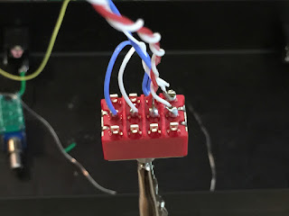
For the bypass function I bought 4PDT switches from Mammoth Electronics (mammothelectronics.com) that worked nicely for this project. These switches let me completely disconnect the potentiometer and connect the input jack directly to the output jack when placed in the bypass position.
For wire I chose mil-spec teflon-jacketed silver-plated copper, I like this wire because no matter how hot you get it with a soldering iron the jacket does not melt. There is a guy on eBay regularly who sells this wire for about 1/3 what it costs in stores (if you can even find it). He often has it in 10 different colors too.
The holes in the capi-gear circuit cards are very tiny, I used 24-gauge stranded-wire and after it was tinned it barely fit through the holes.
The output jacks are Switchcraft, I kept the grounds discrete for the two channels to avoid even the slightest ground-loops.
Doing neat solder work on the capi-gear circuit cards requires some very thin solder, you don't want giant blobs here.
BUILDING IT
This is not a difficult gadget to build because it's completely passive. The Capi custom potentiometers are doing all the heavy lifting, the rest is just execution of the construction.
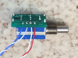
Installing the little circuit cards on the Capi custom potentiometers is one of the most difficult parts of this project, there are 13 little legs that need to get aligned for the circuit card to go on to the pot. Equal doses of patience and bright light can help get this done with minimum frustration.
Installing the little circuit cards on the Capi custom potentiometers is one of the most difficult parts of this project, there are 13 little legs that need to get aligned for the circuit card to go on to the pot. Equal doses of patience and bright light can help get this done with minimum frustration.
Here is my original engineering schematic for the 4PDT switch
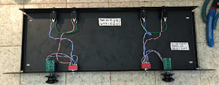
After drilling all the holes in the enclosure I gathered all the parts together and got to work with the soldering iron. Sometimes I build right in the enclosure but for soldering things like these toggle switches and the Capi pots I did the soldering outside the box.
I broke all the assembly down to sections. First I soldered the toggle switch assembly for each channel,
then the potentiometer assembly for each channel,
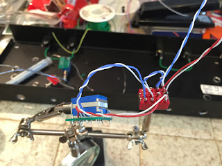
then soldered them together with precut jumper wires.
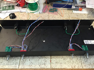
Next I installed the two switch-potentiometer assemblies into the enclosure
and finally connected the wires to the jacks in the rear.
HOW DOES IT SOUND?
This box has no sound of its own, it's absolutely transparent in my listening evaluations. I'll give it a more thorough technical bench test in the near future but in-use it does exactly what I wanted which is to transparently reduce the level of the left and right balanced audio signals.
The stereo attenuator is electrically placed after the Warm Audio EQ's and right before the inputs of the API 2500 stereo mastering compressor in our mastering rack. This allows any gain or boost from the Warm Audio EQP equalizers to be reduced to unity before entering the API 2500 bus compressor.
IN USE
I fed a test tone into my mixing console, lined up each output meter on the mixer for 0-VU, set the API 2500 meters to input and used the new attenuator level controls to match the levels coming out of the WA EQP's so the API reads 0-VU just like the console output. Perfect level every time, quick and easy.
Now when I switch the mastering-loop insert on the Neve mixer in or out of the circuit the volume remains the same, all you hear is the affect of the equalizers and compressor when they're switched in to the circuit, without any volume boost or cut.
Thanks to that custom pot that capi-gear.com makes and sells this project was possible and a great success. We got exactly the results we were wanting. The total cost of this project was somewhere around $130 worth of parts. The usefulness of this tool in my recording work is immeasurable.
Good music to all!
MORE ATTENUATION TO COME
I ordered seven of the capi-gear triple-gang custom pots. Two were used to build this stereo mastering attenuator box.
Next project is going to be a four-channel version of this attenuator setup to use with my API 3124+ so I can attenuate the balanced outputs.
The seventh pot is going into a custom box that will become part of our audio test oscillator, the attenuator will provide a readily available precision balanced output level control for easy adjustment.


